Iridium ACARS Decoding.
Navigation: home
There is a solid amount of ACARS messages being sent via the Iridium satellite constellation.
To set expectations right up front, there are no position reports like ADSB/C. So no chance of directly plotting aircraft pixels on a map, also the way Iridium works, routing messages between satellites in LEO to the nearest satellite that can ‘see’ a ground station (gateways are located in Tempe, Arizona (USA) Fairbanks, Alaska (USA) Svalbard, Norway (Europe) Punta Arenas, Chile (South America)), you often only get a fragment of the ACARS message. And voice? Very delayed, very time consuming, very CPU intensive for just a few seconds of a random unknown call audio (ie, more than just aircraft voice calls are carried by Iridium, so you cant just decode aircraft calls), so we are not even going to discuss it.
Currently there are a solid number of avgeek ground stations scattered around mainland USA and a few around Europe / UK which when combined are seeing around 24,000 Iridium ACARS messages a day.
In Jan 2022 we started looking at it seriously, so all this is very new and thus a bit rough around the edges, but here are some tips to get you started. If you want to get technical, this doc is a good read.
Sep 2022 Iridium has picked up a LOT of interest in the past few months with some very interesting posts on the ACARS groups.io email list.
Seems that a good amount of military aircraft (All USAF KC-135 for example) are going to be moving from Inmarsat L-Band to Iridium. There also have been some really solid appreciation for Iridium ACARS messages given via Twitter from the website power users. It’s clear that this bleeding edge mode has a great deal of untapped potential.
Insert usual call for more feeders here…
Check out the Iridium page on [tbg.airframes.io] to see the sort of data you will be getting. Iridium is the second most expensive ACARS mode (after C-Band), so be sure it has some data you really care about. If you live in an area already covered (check the about page for example global ACARS Iridium stations), you might want to think twice about the expense. Your data will help, but don’t go hungry or cold to provide what we already have on the sites.
For a quick soup-to-nuts Iridium ACARS primer, thebaldgeek did a Tweet thread that got unrolled, view it here
Parts required to build an Iridium ground station
Antenna
I started out using the RTLSDR v2 patch antenna since its only meh at Inmarsat and so I had an unused one kicking around. While not the best antenna for Iridium (its directional and has a mystery SAW filter in the LNA), its really not too bad given it’s price and availability, if its all you can get, then give it a go by mounting it outside, looking straight up ie, flat, or angled in any direction that does not have obstructions (trees etc).
Some people have hand built themselves a RHCP L-Band patch antenna, since it has less forward gain, the home made ones are an option if you are so inclined. Be sure and couple it with a solid L-Band LNA - ie, a filtered one, not a wide band LNA.
I jumped on eBay and picked up a combined GPS and iridium dome antenna and will report back on how it goes once we get some air time with it - Update: July 2024, its not great.
Do note that there are very few active (built in LNA) Iridium antennas since transmitting up to the satellites is very common. That said, I have found one that I really like: HC610. (There is also a passive version of this antenna, so that might be an easier to find and buy than this active one). Note that the HC610 has some nice out of band filters to help cut down on the very busy L-Band crud we are not wanting to hear. This filter / amplifier combo in the HC610 makes it perform well beyond its tiny size.
In short, thus far, out of the 6-10 antennas tbg has tested, the HC-610 is by far and away THE best Iridium antenna by a good margin. (And when coupled with the Airspy R2 SDR no better combo has been found).
When it comes to mounting the HC610, there are a few options depnding on your setup.
If you have a vertical pole and need it to sit on top: HC610 pole mount
If you have a vertical pole, but need it to mount out the side. A 3D printed option is this bracket
Do note that if you are printing this yourself, take a note if your coax connector will fit. The print as shown is for a coax with an SMA on the antenna end. If you have an N-type to SMA adaptor, you will need to mod the file before printing or drill it out (do note that drilling 3D material can be messy/ugly). Either way, keep the top of the bracket where the HC610 sits as flat as possible so you can put some sealent around where the O ring is to keep the water out of the antenna / coax.
If you want to wall mount the HC610, there is another 3D print for that
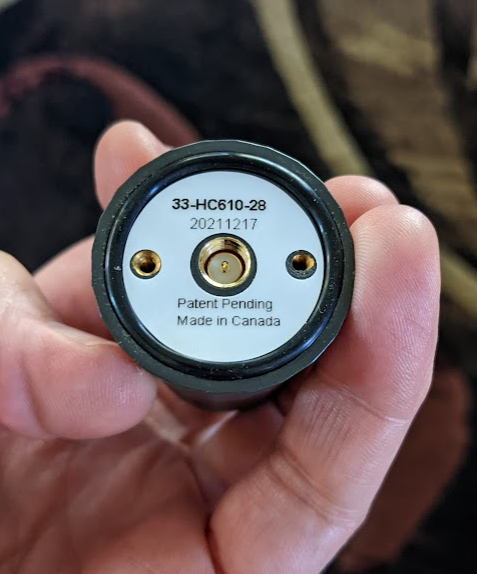
This is the view of the bottom of the antenna. Note the male connector.
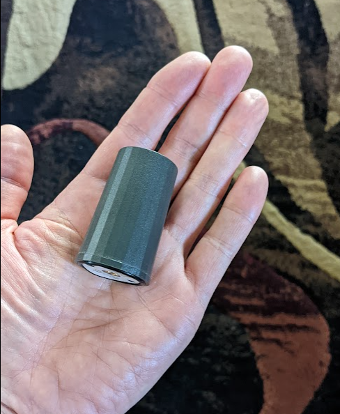
This helix is very small, should be able to mount it outside in the clear view of the 360 deg sky very easily.
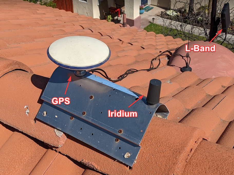
Mounted next to my GPS (galmon) antenna. Note that the L-Band patch is looking at the 54w Inmarsat, not Iridium.
If you are using an active antenna or LNA be sure and enable the Bias-T on your SDR via its config file, or use a physical Bias-T power injector (which is what I do because I am testing a lot of different SDRs and they all are a pain to turn the bias-T on in the config file - some don’t even support Bias-T - some (RSP1a) only supply 10’s of milliamps via the Bias-T and depending on your LNA you might have issues supplying enough power.).
Bottom line, you want an L-band RHCP omni directorial (360 deg) antenna with a clear view of the sky, good LNA and good quality coax for Iridium.
LNA
There are a few wide band amplifiers that cover 1.6Ghz, most are pretty noisy since they run wide open (unfiltered) and have far too much gain. Best LNA for Iridium is an L-Band specific one.
The Nooelec Iridium+IR LNA has amazing performance. Well worth the money and Bias-T hassels to drive this amplifier.
At a quick glance, you may assume that there are a few Nooelects that seem to cover this band, but they don’t all cover the full range of Iridium frequencies. Nooelec have a really helpful page on their SAWbird LNA range, take some time to read it before making your purchase. Here is a tip, Iridium is pretty loud. You may not need the extra gain of the + LNA version. Also note that the + draws an extra 150mA. So for example, if you are using an RSP1a SDR, its Bias-T can only supply 50mA, so the base SAWbird LNA is (should be - might be) fine at 30mA draw, the + at 180mA will not work. In the case of Iridium, the extra 10db gain is probably not needed so this combo would work fine depending on your antenna, coax quality and length. (Of course, once again, to really press this home, you can and should just use a physical Bias-T and not have to worry about any of this).
Of course, if you are using the HC-610 antenna, you don’t need an LNA (And for sure you should NOT run an active antenna AND an LNA, that is not a good idea at all - please don’t subscribe to the ‘more gain is always better’ school of wrong).
SDR
I normally like the RTLSDR v3 for this sort of thing (all things ACARS and L-Band). Its very affordable and very quick and clean to get running. The problem with the RTLSDR is that it only covers around 2Mhz bandwidth and that is only a very small number of the Iridium data channels.
I am testing the LimeSDR Mini v1 (10mhzBW), RSP1a (9mhzBW) Airspy R2 (10mhzBW), Airspy Mini (6mhzBW) and HackRF (10MhzBW) and am getting good ACARS numbers from most of these, easily more than 4x the data from the RTLSDR due to all of them covering more bandwidth of various amounts.
The RSP1a would be a viable option if not for the rather unstable API Linux driver they ship. It is very CPU intense (wasteful) and as I said, somewhat crash prone. (This is not just an gr-iridium issue, those using the RSP1a on dumphfdl have the exact same issue). The hardware is great, the Linux software is lacking. There are currently no Windows Iridium decoders that I know of. (No idea about Mac).
If you follow my Twitter (sorry), you might have seen a month long thread about if the RSP1a really can cover the full 10Mhz bandwidth required by Iridium and October 24th 2022, we have an answer. Sort of! (but again, good luck with the driver).
For the current top choice, the Airspy R2 simply connect the R2 to a USB 3.0 port and you will get all the Iridium data there is to get (assuming your CPU can keep up).
To be clear. We don’t actually know for sure if you require a 10Mhz bandwidth SDR or not. It seems that there is no ACARS in the top bit and so an 8Mhz might be Ok. But, we do KNOW for sure that you need a computer to drive it to get all the data channels on Iridium. (Do note that the Raspberry Pi 4 is just not powerful enough for Iridium). Most bleeding edge stations are running 10meg to see whats out there in this new mode.
Software. MUCCC - iridium-toolkit and gr-iridium
If you want to build from source the repo can be found on the Chaos Computer Club München GitHub. I really don’t recommend building from source, gnu-radio is not trivial to build and nor is the gr-iridium toolkit. Ubuntu 22 is getting a bit better with gnuradio being in the repo, but there are still some hoops to jump through to get all the pieces and parts working together from what I am told - I simply use DragonOS_FocalX where its all plug and play.
Note that none of the Iridium tools use a gui, so you must run it all via the desktop shell terminal on the DragonOS computer (or via PuTTY with DragonOS). I did my testing on a VMware instance on my Windows PC since you need USB 3.0 and plenty of CPU power to drive your SDR to the required 10Mhz BW and decode all the burst data.
Computer - CPU power is critical
The decoding of such a wide bandwidth of such bursty data is very CPU intense. You will need a USB 3.0 port to pass the data smoothly (USB 2.0 is a bit of a bottle neck - Please don’t argue that USB2.0 is good enough. You are wrong. Its not enough. You MUST use a USB3.0 port that is not shared with any other SDRs or USB 2.0 devices like keyboards or mice. USB will downgrade any USB port to the slowest device on the port.).
Again. To be very very very clear. Stop arguing with thebaldgeek that the Airspy R2 is only a USB 2.0 device and so USB2 is fine. ITS NOT FINE! Connect it to a USB3 port (the blue ones) that does not have ANY other USB devices on it (lsusb and sudo lsusb -t are your guides here).
Ok, fine, so you want to argue, look at this way, you have spent a lot of money and time setting up an Iridium station, if you want to plug into a USB2 port and get low 50’s bursts and ~50 to 60% ‘Ok_ave’ numbers, thats on you. Just don’t DM tbg and ask how to make it go better on USB2.
For computer starters, the Raspberry Pi5 and Pi4 do NOT have enough power to decode more than about 2mhz, ie, the output of the RTLSDR v3. So yes, you can get started and see a few messages, but you will be missing out on over 80% of the aircraft in your area and you will have to chose between getting ACARS and seeing your map coverage, one or the other, the Pi5/4 and RTLSDR v3 can not decode both. (Look down this page a bit to see why, the map data is at one end and ACARS data at the other end of the 10Mhz spread).
Our KBOS station is running: i3-12100 CPU, H670 chipset. That seems to be doing the job very well. A few other stations are running the Beelink N95 and N100 NUC or Trigkey NUC clones and seem to be very happy reporting good decode rates. We want to test the Odroid N2. A guy used a Steamdeck with good numbers.
A few other stations are using old laptops, i5, i7 and are working well (i5 is touch and go). One reported his very old i7 could not keep up and he had to upgrade the system he ran the Iridium code on.
RAM is not as critical, around 2-4mb or more is enough. HDD space requires a minimum of 32GB for DragonOS_Focal.
Personally I am running DragonOS_Focal on a VMware player machine on my Windows PC sharing 6 cores and am very happy. July 2024 update. A windows reinstall broke USB3 virtual box support and after weeks of struggling, I gave up, bought a Beelink N95 for $130 off Amazon and was back up and running in about 15 minutes with DagonOS_FocalX. Wish I had not wasted my time on the vmWare / VirtualBox drama.
You will know if your CPU is up to the task based on how many dropped frames you see. Roughly the make/break is to have a ‘ok_ave’ of MORE than 70%. If you have less, you are plugged into a USB2 or a USB3 with a shared USB2 bus/device or your CPU is choking.
Getting Started
Once you install DragonOS_FocalX on an i5 or better x86 computer with a USB 3.0 port, you are ready to start.
The very first thing you MUST do is run the command (NOT as sudo, just as your user - this is important its done just as your usual username/command prompt) volk_profile
What this does is run a whole bunch of math problems in different ways and figures out your CPU profile and the fastest way it computes stuff.
It then writes its profile result to your userID and then when you run Iridium and other SDR stuff on DragonOS this profile is used and so you end up with a much more effective math computer.
This should be done on every PC and every fresh install of DragonOS.
Do note it takes about 10 to 20 minutes and you should ovid doing much on the computer while it runs. Just step away and let it do its thing.
View your Iridium spectrum!
Once that is done the next critical step is to view the Iridium RF spectrum from your antenna/LNA/coax/SDR installation.
This is a very critical step as you may not see a problem just from looking at the gr-iridium decoder numbers (more, much more about them down the page).
For example, if you happen to have some sort of burst interference in your install/area, the decoder will have very high CPU use, but your decoded data numbers will be poor and you won’t know why.
So, if you are running DragonOS, then open SDR++ from the start menu, select Airspy from the radio list and start viewing the spectrum / waterfall at the Iridium center frequency of 1.622GHz.
Here is what my HC610 antenna and LimeSDR looks like.
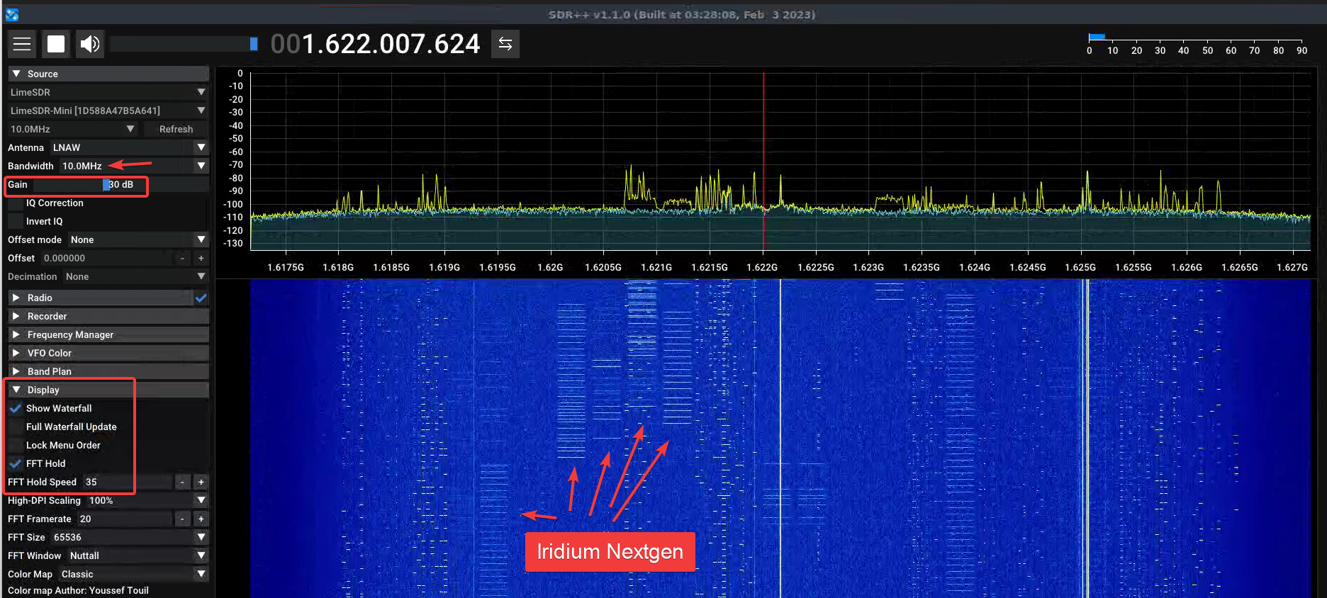
Note that it’s important you set the bandwidth to 10Mhz just like the gr-iridium decoder will use.
Note that the gain for the Lime is different from the Airspy. For the R2 you probably will be around the 17 gain value - but do keep reading!
It helps if you set the display to FFT Hold so you can see the peaks of the Iridium data bursts. (This is actually a pretty important visual aid).
Now for reading the spectrum. You should see the little bursts floating down. (Each of those ‘rain drops’ have frames of data in them). You might also see (hope not) some continuous carriers. It’s important to know that Iridium does not have ANY continuous carriers, so any you have are in your area. You can see that I have about 3. Disconnecting the antenna removes 2 of them. So one is from the USB 3.0 setup on my SDR / PC. Those other 2 are RF interference in my area. I could try and track them down, but …. yeah… They matter as any bursts that occur on them can not be decoded and the Iridium decoder will be constantly trying to decode them - using CPU do so. So 1-3 of them should be ok, but if you have many, your station performance will suffer.
The main key to look for is if you have any pulsing or bursting interference. I waited till a few Iridium Nextgen satellites passed over before taking the screenshot, those narrow bursts that come and go are fine, but anything that flutters all the time is bad. Very bad. Much much worse than a carrier as the gr-iridium decoder will spend endless CPU cycles trying to decode it and your station will suffer. So those you MUST find and fix.
Gain setting.
Setting the gain is critical with any SDR install, be it voice, or data, HF, VHF or satcom.
Move the gain to zero. Ignore the waterfall, just look at the spectrum.
Slowly move the gain up. Look at both the noise floor and the peaks of the signals.
As you move the gain all the way to max you will see the noise floor just keep rising, but the signal peaks will at some point stop getting higher. They will just get crushed between the rising noise floor and their max height will just remain the same. This is where the peak hold is helpful with Iridium, so you can see what the peak of the bursts are.
Move the gain up and down very slowly, one click at a time till you have the tallest hight on the signals and lowest noise floor. Make a note of that number.
You don’t want to crush your signal, you want to ensure your SNR, signal to noise ratio, is a high as possible. Tall peeks, low noise floor. Big gap between the peak and the static is what you looking to get dialed.
Decoding Iridium ACARS.
For now you are going to open a few terminals, we are working on an script to run it and keep it running (it does crash now and then), but for now, this is the best way to get going…..
This guide assumes that you would like to share your Iridium data with the world and thus send it to thebaldgeek and airframesio so it can be added to the main Iridium page and more. You can also open another terminal and use the same process to send data to yourself on another UDP port number in another terminal.
Here is the big picture, we are going to make a python file (acars.py) that will take the output from the Iridium decoder and send it via UDP to thebaldgeek ingest server. (Note, this WONT work for airframes.io - more on how to feed them at a future time). You will have one terminal to extract the raw data and another terminal to decode the ACARS messages and to send the data to my site. (Optionally, there is a third terminal for your local map if you would like to see your coverage).
Docker
If docker is your poison, you have an option Iridium Docker by jkrasuk
Lots of terminals
Terminal One
The airspy R2 is a very popular SDR for Iridium for good reason. It has a nice stable driver, is affordable, in stock and covers the required 10Mhz.
If you are using the R2, here is a great starter conf file….
Open a blank file from your home directory and copy it in….
cd ~
nano r2.conf
Copy paste in this text and save it with ctrl+o to write it and then ctrl+x to exit out of the editor.
[soapy-source]
driver=airspy
device_args='bitpack=1,biastee=false'

sample_rate=10000000
center_freq=1622000000
bandwidth=10000000

# Linearity Gain
gain=16
I know that none of you reading this will need the software Bias-T, so it can be left as ‘false’
Run the extractor from any directory: (This assumes you are using the Airspy R2 with the config file we just made, change the .conf file to match your SDR and edit it to turn on the Bias-T if required).
iridium-extractor -D 4 --multi-frame ~/r2.conf | python3 -u /usr/src/iridium-toolkit/iridium-parser.py -o zmq
To be clear, if you not using an R2 look/path that command in the /usr/src/gr-iridium/examples/ directory and find your SDR and tweak that file to best set it up.
A quick word about the -D 4 part……
Decimation is a way of breaking up the 10Mhz bandwidth into more CPU digestible sub parts (with a small overlap to not miss any burst that happen to fall on a seam).
Its strongly recommended that you do run with some decimation. There is a strong mathematical link between decimation, SDR sample rate and the total bandwidth. gr-iridium will do a sanity check when you start it and let you know if you are hallucinating with any of the combinations.
You should test -D 8 and -D 4 as a guide. Each change should be given a few hours to soak and get stable numbers.
Because of the LEO nature of Iridium, you cant rush things. Play the long game and get it right.
Once up and running you are going to get a line of status numbers per second:
1666645162 | i: 351/s | i_avg: 392/s | q_max: 24 | i_ok: 79% | o: 751/s | ok: 82% | ok: 291/s | ok_avg: 85% | ok: 31170861 | ok_avg: 334/s | d: 8260
Either see the MUCCC GitHub page linked above or scroll down a bit for a full breakdown on each of these values and their meaning.
Your location on the planet (ie Australia has the same Iridium satellites pass over, but less aircraft/pager/phones etc use it downunder) and antenna placement (hint, inside a double glazed window is not going to give very good numbers at all, the foil coating will block most of the L-Band signal, trust me on this, better in the middle of a wall or even in an attic) will change your numbers. Just a reminder, max gain is not always best gain, you set it via the spectrum right? (Tip, the Airspy R2 gain is from 1 to 21).
You want to keep reading as your Iridium station will live or die by understanding these numbers scrolling up the page.
You will spend a fair bit of time looking at these numbers scroll past as you set up and tune your station. Test each station/software/hardware change over at least 1 hour (24 hours is better) to give time for few satellites and aircraft using Iridium (not all do) to pass over your station location. This is not a quick fix / win game, take your time, make notes, the satellites are in a LEO and don’t always pass directly over your location.
If you want to feed thebaldgeek your Iridium ACARS data (please consider it, its the only site so far that does the Iridium aircraft registration lookup and splits civil / military into tables) then you will need to create the following file and DM thebaldgeek to get the port number to feed your data.
Terminal Two
Type nano acars.py, then copy/paste in this text:
#!/usr/bin/env python3

import sys
import select
import time
import socket


ap = ("thebaldgeek.net", 123456)
sk = socket.socket(family=socket.AF_INET, type=socket.SOCK_DGRAM)
def sendOverUdp(line):
    try:
        bytes = str.encode(line)
        print(len(bytes))
        if len(bytes) < 65300 :
           sk.sendto(bytes, ap)
    except Exception as e:
        print(e)

def no_input():
    print('no input')

while True:
    line = sys.stdin.readline()
    if line:
        sendOverUdp(line)
    else:
        time.sleep(1)
else:
    no_input()
Change the thebaldgeek.net to what ever host you want to send your UDP ACARS messages to, and also change the port number from 123456 to the port you are using or thebaldgeek gives you. Then save and exit nano.
Next run this command:
python3 -u /usr/src/iridium-toolkit/reassembler.py -i zmq: -m acars -a json --station YOUname-IRIDIUM-YOUairport | python3 ~/acars.py (Swap out YOUname for say your ham call or your initials, swap out YOUairport for your nearest large airport ICAO code (mine is KRIV) and let me know what it is so I can filter out your data for you).
Do note that nothing will show in this terminal until you pickup your first ACARS message. Depending on how many Iridium aircraft there are in your area, it could take a moment or a few minutes or even an hour, then a single number will show up, you will see a number for every message. The number is the size of the ACARS message once its decoded.
What this is doing is taking the raw data from the zmq feed, looking for -m (mode) acars messages and then formatting them into JSON and sending them to the script which then sends it to a URL and port number via UDP.
If you want to feed airframes.io your Iridium ACARS data contact them or thebaldgeek. There are at least three scripts floating around at the moment to feed them and I’m honestly not sure what the state of play is currently (June 2024).
Terminal Two point Five
if you want to see your ACARS messages stream past, then open another terminal and just connect without the pipe to the acars.py, like this…..
python3 -u /usr/src/iridium-toolkit/reassembler.py -m acars zmq:
Terminal Three - Your local map.
Now, if you want to get your local map running: (Its really just a satellite spot beam map, NOT a station coverage map. This is optional, but cool to see).
cd /usr/src/iridium-toolkit/html
sudo nano example.sh
On the second bottom line, if not already done, add a 3 at the end of the word python and be sure and change the IP address for your PC (your PC might not be 192.168.1.122), so it should read
python3 -m http.server --bind 192.168.1.22 8888
Save and exit nano
Tip you can find your IP address by the command ip address it will be in there.
In the terminal run the example file: sudo ./example.sh
At this point, you can visit your PC’s IP address from any browser on your network and look for the map, so in my case http://192.168.1.122:8888/map.html
Let that run. You should see the sats and beams update around once a minute.
Keep reading if you would like to share your map with thebaldgeeks current global Iridium map (please and thanks).
Do note that you MUST be running the ./example script to generate the sats.json file.
If you are feeding your map to thebaldgeek, you MUST have the local map running to feed it to the master map on tbg’s site.
Terminal Four - Sending me your map data.
Optional. If you want to add your map coverage to the central global map that I tweet now and then.
Type nano map.py, then copy/paste in this text:
#!/usr/bin/env python3

import sys
import select
import time
import socket

uid = "ktbg"
ap = ("thebaldgeek.net", 123456)
sk = socket.socket(family=socket.AF_INET, type=socket.SOCK_DGRAM)
def sendOverUdp(line):
    try:
        bytes = str.encode(line)
        print(len(bytes))
        if len(bytes) < 65300 :
           sk.sendto(bytes, ap)
    except Exception as e:
        print(e)

def no_input():
    print('no input')

while True:
    line = uid + sys.stdin.readline()
    if line:
        sendOverUdp(line)
    else:
        time.sleep(1)
else:
    no_input()
You will need to change the UID from ktbg and tell me what you set it to be and then change the port number that I will give you and this will allow you to send your local map data to the global map. (View the master map on the home page of the site).
Next run this command:
pip install https://github.com/joh/when-changed/archive/master.zip
This will install a python script that will look for changes to a file.
Its VERY important that you CD into where it was installed:
(change ‘ubuntu’ for your user name home directory if needed) cd /home/ubuntu/.local/bin
Now run the file watch which will send me your sats.json rougly once a minute and your coverage will be added to the master map on my site:
./when-changed /usr/src/iridium-toolkit/html/sats.json cat /usr/src/iridium-toolkit/html/sats.json | python3 ~/map.py
Is it working? Tuning by numbers
Iridium is a bit of an odd mode. It really rewards a bad antenna and poor performing SDR. What do I mean by that?
The worse the antenna, the better your ‘Ok’ numbers look.
A poor performing antenna or a bad (low) gain setting on the SDR means there are very few bursts of data being received so your computer is able to decode them just fine and thus you get some great ‘Ok’ numbers, but low burst numbers and low ACARS numbers. So really understanding these numbers is key. You want some of the numbers to be large and some to be small, knowing which is key.
As you get your antenna type/location dialed and get your SDR gain dialed using SDR++, your computer CPU load will go up and your ‘Ok’ numbers might go down if your USB port or CPU starts to choke. We are looking for the best burst to Ok number ballance for your CPU.
1678802073 | i: 255/s | i_avg: 343/s | q_max:   14 | i_ok:  86% | o:  638/s | ok:  98% | ok: 250/s | ok_avg:  74% | ok:   39410936 | ok_avg: 254/s | d: 0
1678802074 | i: 335/s | i_avg: 343/s | q_max:   17 | i_ok:  88% | o:  844/s | ok: 102% | ok: 343/s | ok_avg:  74% | ok:   39411280 | ok_avg: 254/s | d: 0
1678802075 | i: 398/s | i_avg: 343/s | q_max:   19 | i_ok:  77% | o: 1007/s | ok:  93% | ok: 373/s | ok_avg:  74% | ok:   39411654 | ok_avg: 254/s | d: 0
1678802076 | i: 365/s | i_avg: 343/s | q_max:   15 | i_ok:  80% | o:  909/s | ok:  97% | ok: 354/s | ok_avg:  74% | ok:   39412010 | ok_avg: 254/s | d: 0
1678802077 | i: 476/s | i_avg: 343/s | q_max:   20 | i_ok:  55% | o: 1108/s | ok:  61% | ok: 293/s | ok_avg:  74% | ok:   39412304 | ok_avg: 254/s | d: 0
Here is a slug of my station numbers. They should give a good feel for what a busy location (Southern California) can produce.
Lets break down the numbers and see what we can learn about tuning up a station….
Column Mnemonic Explanation
1 time Current time in seconds (unix time)
2 i: Live input number of “bursts” detected in the last second. Will change a large amount as the satellites pass over head and vary based on the amount of Iridium traffic the sats are hearing.
3 i_ave: Running average of 2 since program start. If you don’t have any interference, higher is better. North of 100 at the very least for a good location. Aust should be around 50 here. Most of the USA/UK/Euro should be well north of 200.
4 q_max: High-water mark of the sum of the queue size(s) in the last second. ie bursts your CPU has not been able to process and so has put in a queue for latter processing. Lower (less than 50) is better.
5 i_ok: Percentage of bursts with at least one ok frame relative to 2. Not all bursts have frame decodable data, so this is of interest, but not critical as there is nothing we can do either way.
6 o: Number of “frames” after splitting bursts into frames. Not of much use to station owners.
7 ok: Percentage of “ok” frames(8) relative to 2. Since each burst can have up to 4 frames of data, this Ok% can go above 100%
8 ok: Number of frames in the last second that could be extracted & demodulated
9 ok_ave: Average average of 7 since program start
10 ok: Total number of ok frames since program start
11 ok_ave: Running average of 8 since program start
12 d: Total number of candidate bursts that had to be dropped due to queue (4) full (i.e. CPU being too slow). Anything more than zero here is an issue.
Lets break down the table a bit into human terms (if we can).
1 = time. There are some concern’s about this time being different across computers. This is understandable as not all computers are running NTP (time sync). Each ACARS is timestamped on my site, so for now, thats the setup.
2 i: = Raw bursts. This is a big key to how well your front end is working. The more bursts you see, the better your antenna and SDR gain is dialed. Iridium traffic dependent. (Location and time of day variable).
Do note that this number will go up and down as the LEO satellites fly past over head. And not just the number or azimuth of the satellite, but also the amount of traffic on that satellite at the time. You need to keep a mental track of this number, but is first number is the one that gives the best metric of how well the RF aspect of your station is working.
If you are only seeing 10 to 80 bursts typically, your system will seem to be working great and you will have a high ‘Ok’ number, you will even see some map coverage, but your ACARS message rate will be very low. ie, low volume of data in, low volume of data out.
3 i_ave: = average of 2. Helpful since the sats are really moving and the amount of traffic on any given sat changes from moment to moment.
4 q_max: = Bursts you PC cant process due to being busy. Helpful to know how hard your CPU is backlogged. Should be less than 20 most of the time. High numbers indicate not enough CPU power to decode the bursts.
5 i_ok: = We cant do anything about this number. Not all bursts have decodable data in them.
6 o: = How well your computer has pulled frame data out of the burst. Not always linked to CPU, not really much use to the station owner.
7 ok: = Live Ok frames of data in each burst. Since each burst can have 4 frames, you can see more than 100%, which is pretty cool.
8 ok: = This will somewhat reflect 2. High number in, high samples decoded, low in, low decoded. However, its also linked to the amount of data in each burst.
9 ok_avg: = Running total of how your CPU is keeping up with 1 and 4, but also to some extent 7. So good bursts in (clean RF), small que depth and good amount of decodable frame data in any given burst that your CPU could decode.
10 = Total number of frames decoded. Just a big (hopefully) number that goes up over time. (Note, worth considering having a batch job to stop/start the extractor at midnight so this number does not get too large and it might be nice to log the daily total - on the to-do list).
11 = Important number. Higher is better. Really a heath check on all the preceding numbers (and the last one).
12 = Dropped frames. Should be zero ideally. If consistently showing a value, your CPU is underpowered for your location/data rate.
Lets try and break that down even more…..
2, 3 and 5 (i, i_ave and i_ok) are RF metrics. They show how well your location, antenna, LNA, coax are working. Should be well north of 100. North of 250 would be better still. Use antenna type, placement, LNA type/filtering (GPS and Iridium are close, a filtered LNA helps Iridium) and SDR gain to get up there.
4 and 12 (q_max and d) are CPU metrics. If you have North of 20-30 in your que and dropped samples, your CPU is just not up to the job.
9 should be as high as your computer can push it.
The Fun Part. ACARS messages!
Now that you have a UDP stream of ACARS messages you can perhaps use Node-RED to view them, or save them to your hard drive to view with your text filter software / application.
airframes.io has an ingest script, so reach out to me or Kevin to get that. Please feed Kevin (and me if you like) because when you do that you will be part of a global system using this very challenging mode.
Speaking of ‘fun’, it seems that once again and aircraft builders are tormenting AVGEEKS the world over as they use different ICAO/Rego/ModeS combos in their messages to identify their aircraft.
thebaldgeek is keeping a list of ‘unknown’ aircraft and if you like tracking down those sorts of things, everyone would love your help to figure out the ones in the table. Once they are ‘known’, their Iridium ‘code’ is put in a CSV file and used site wide for identifying the aircraft no mater what mode they show up on.
At the moment, ADSBEx (or any other flight tracking service) does not include these…aaahhh… ‘special’ Iridium codes, so tbg.airframes.io is the only place these Iridium aircraft are decoded and put into tables / database.
thebaldgeek is sharing these codes with the airframes.io guys as he does not want to be a data island and wants to share all the information he can so as many people as possible can benefit.
Simplex Frequency Allocation
| Channel Number | Center Frequency(MHz) | Allocation |
| 1 | 1626.020833 | Guard Channel |
| 2 | 1626.062500 | Guard Channel |
| 3 | 1626.104167 | Quaternary Messaging |
| 4 | 1626.145833 | Tertiary Messaging |
| 5 | 1626.187500 | Guard Channel |
| 6 | 1626.229167 | Guard Channel |
| 7 | 1626.270833 | Ring Alert |
| 8 | 1626.312500 | Guard Channel |
| 9 | 1626.354167 | Guard Channel |
| 10 | 1626.395833 | Secondary Messaging |
| 11 | 1626.437500 | Primary Messaging |
| 12 | 1626.479167 | Guard Channel |
Duplex Channel Band
| Sub-band | Lower Edge (MHz) | Upper Edge (MHz) |
| 1 | 1616.000000 | 1616.333333 |
| 2 | 1616.333333 | 1616.666667 |
| 3 | 1616.666667 | 1617.000000 |
| 4 | 1617.000000 | 1617.333333 |
| 5 | 1617.333333 | 1617.666667 |
| 6 | 1617.666667 | 1618.000000 |
| 7 | 1618.000000 | 1618.333333 |
| 8 | 1618.333333 | 1618.666667 |
| 9 | 1618.666667 | 1619.000000 |
| 10 | 1619.000000 | 1619.333333 |
| 11 | 1619.333333 | 1619.666667 |
| 12 | 1619.666667 | 1620.000000 |
| 13 | 1620.000000 | 1620.333333 |
| 14 | 1620.333333 | 1620.666667 |
| 15 | 1620.666667 | 1621.000000 |
| 16 | 1621.000000 | 1621.333333 |
| 17 | 1621.333333 | 1621.666667 |
| 18 | 1621.666667 | 1622.000000 |
| 19 | 1622.000000 | 1622.333333 |
| 20 | 1622.333333 | 1622.666667 |
| 21 | 1622.666667 | 1623.000000 |
| 22 | 1623.000000 | 1623.333333 |
| 23 | 1623.333333 | 1623.666667 |
| 24 | 1623.666667 | 1624.000000 |
| 25 | 1624.000000 | 1624.333333 |
| 26 | 1624.333333 | 1624.666667 |
| 27 | 1624.666667 | 1625.000000 |
| 28 | 1625.000000 | 1625.333333 |
| 29 | 1625.333333 | 1625.666667 |
| 30 | 1625.666667 | 1626.000000 |
Stop reading here, the notes below are mostly wrong and are just for history.
Note that I used to run a global Iridium coverage map, but the URL was getting ‘attacked’ to try and break into my network, so I took it down.
If there is enough interest from the handful of Iridium feeders, I can put it back up and just let a few people know about it.
Sep 2022. Its back! Feeder only perk. Follow me on Twitter to see regular map updates.
Closing thoughts / to-do
May 2023 I had a chance to chat for many hours with one of the MUCCC guys and got a better feel for the scrolling numbers and so made a big update to this page around that time.
I have always wanted to extract them and plot them on a graph and it turns out that the MUCCC do just that, but in 24 hour retrospective batches. But, they did give me a few clues on how we might do it live.
That investigation is now on my to-do list. Yes, I will probably use Node-RED, but the method should apply no matter so will see what I can get running and will share any notes here on this page.
================================================================================
Really really stop reading now.
Getting the lastest version
cd ~
wget https://github.com/muccc/iridium-toolkit/archive/refs/heads/master.zip
unzip master.zip
Now path to where that unzipped ie, /home/yourusername/iridium-toolkit-master/
Pipe and tee
We are going to pipe the data into Node-RED via UDP.
To do this, we need a way to get the stdout data into a UDP stream, we will use the iridiumlive python code to do that.
Pull the code down from the github and save it in a file (or just cut paste it into a nano editor).
Change the IP address in the code to match your Node-RED computer and pick a different port, but note the number.
I strongly suggest putting the port number in the file name you save as you may end up using a few of these files to move data around (I have three).
My files are iudp55667.py and iudp66778.py Obviously, the port number is the same in the python code as the file name and the same number is used in the Node-RED UDP in node.
You will need to chmod the files to make them executable.
We can dump everything at once into Node-RED, but its a firehose, so lets just get ACARS going for a start.
iridium-extractor -D 4 --multi-frame rtl-sdr.conf | python3 -u ./iridium-parser.py -p | python3 -u ./reassembler.py -m acars | python3 /home/ubuntu/iudp55667.py
You can see we are piping the data from each application to the next. The -u tells python to unbuffer the data. Note you may or may not have to call out ‘python3’ depending on what versions of python you have installed on your Pi, I have both v2 and v3, so need to call out which to use (you must use v3 for the iridium-toolkit).
Now on the Node-RED end, you can put your UDP in node and a debug node and after a few minutes you should see your first Iridium ACARS message pop up.
If you want to see short burst data messages, in the command above, swap -m acars for -m sbd You will see more sbd messages than ACARS, so that might be a good sanity check.
What if you want both on different streams? Use a tee.
iridium-extractor -D 4 --multi-frame rtl-sdr.conf | python3 -u ./iridium-parser.py | tee >(python3 -u ./reassembler.py -m acars | python3 /home/ubuntu/iudp55667.py) | python3 -u ./reassembler.py -m sbd | python3 /home/ubuntu/iudp66778.py
Now add a second UDP in node and a second debug in the Node-RED editor and you will have ACARS on port 55667 and sbd on port 66778.
How about three feeds. One to IridiumLive, one to ACARS and one to sbd….
sudo iridium-extractor -D 4 --multi-frame ~/iridium-toolkit-master/rtl-sdr.conf | tee >(python3 -u /usr/src/iridium-toolkit/iridium-parser.py -p /dev/stdin /dev/stdout | python3 /home/ubuntu/u15007.py) | python3 -u /usr/src/iridium-toolkit/iridium-parser.py -p | tee >(python3 -u ~/iridium-toolkit-master/reassembler.py -m acars | python3 /home/ubuntu/u9998.py) | python3 -u ~/iridium-toolkit-master/reassembler.py -m sbd | python3 /home/ubuntu/u29998.py
If you get sick of seeing the status message scrolling up the page in the terminal, you can send it to null like this:
iridium-extractor -D 4 --multi-frame rtl-sdr.conf 2>/dev/null | python3 -u ./iridium-parser.py | tee >(python3 -u ./reassembler.py -m acars | python3 /home/ubuntu/iudp55667.py) | python3 -u ./reassembler.py -m sbd | python3 /home/ubuntu/iudp66778.py
Now you just get the UDP count of real messages.